Contact Us
Contact our corporate or local offices directly.
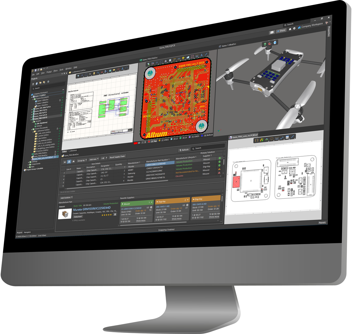
Welcome to Altium Designer, which is a complete, end-to-end design environment for electronic printed circuit board design. Altium Designer enables you to bring your ideas to life with the most efficient and collaborative PCB design environment available. From a tiny, foldable rigid-flex board that goes into a hearing aid, to a large, 20+ layer high-speed network router, Altium Designer works with you to deliver a successful design.
The way you work in Altium Designer is much like other Windows applications in that commands are accessed through familiar menus, graphical views can be zoomed and panned using standard Windows keyboard and mouse actions, and many of the commands and features can be accessed through keyboard shortcuts.
Where Altium Designer differs from other Windows applications is the way that it brings all of the editing tools that you need into one environment. That means you edit the schematic and lay out the printed circuit board in the same software application. You also create the components, configure the various output files, and can even open the ASCII outputs in that same environment.
The 64-bit application that you launch is referred to as the X2 platform. Each different document type opens inside the X2 application with the appropriate editor-specific menus, toolbars, and panels appearing automatically as you move from one document-kind to another.
Why are all the tools inside the one environment, you ask? Doing this allows you to shift your focus from being tool-oriented to being design-oriented. Working in a design-oriented environment delivers you, the designer, significant advantages including:
These are just a few examples of the many advantages a design-oriented environment delivers. Regardless of whether you work as a solo designer, or as a member of a large, geographically dispersed team, Altium Designer delivers an easy-to-use, immersive design space on which you will enjoy crafting your next great idea.

Backing Altium Designer is a comprehensive set of online documentation. Wherever you are in the environment, over a menu command, a dialog, a panel, or a design object, press F1 to display comprehensive information about whatever was under the cursor.
Within this comprehensive information, there are links to related information about how to place it, edit it, or use it. You also will find links to richer content about how it fits into the overall design process.
If you prefer to browse and explore the overall structure, use the navigation tree on the left.
Available shortcuts also are listed in the various panels; look for the shortcut key strokes displayed next to the controls in the panel.
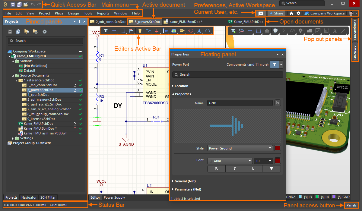
Each editor has its own set of panels, menus, toolbars, and shortcut keys. Panels can be enabled via the button at the bottom right of the application window.
Panels can be docked along any edge of the environment or float independently. When they are docked, they can be pinned open (![]() ), or set to pop-out mode (
), or set to pop-out mode (![]() ). Click a pop-out panel's button to display it; the pop-out speed and delay are configured on the System - View page of the Preferences dialog.
). Click a pop-out panel's button to display it; the pop-out speed and delay are configured on the System - View page of the Preferences dialog.
To move an individual panel, click and hold on the panel name, then drag. To move a stack of panels, click and hold elsewhere in the panel caption bar.
When a panel is being moved over another panel, icons appear to show the available panel splitting options (![]() ). Drop in the center to stack, or drop on one of the four icons to split in that direction. You also can hold Ctrl to inhibit panel stacking.
). Drop in the center to stack, or drop on one of the four icons to split in that direction. You also can hold Ctrl to inhibit panel stacking.
Regardless of the editor currently being used, the Preferences dialog can always be accessed using the ![]() button located at the top right of the application window.
button located at the top right of the application window.
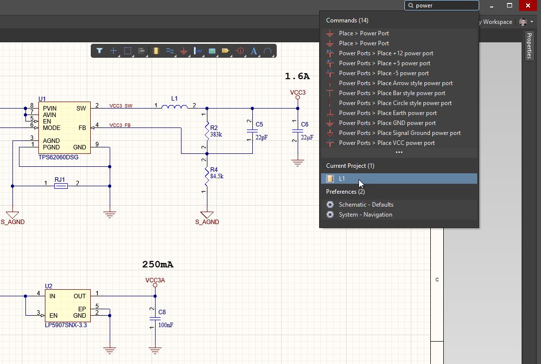
The software also includes a number of handy Search boxes, for example, at the top of the Projects and Properties panels, and for the X2 application itself, located at the top right.
The X2 Search will return:
The X2 environment is highly customizable. Menus and toolbars can be edited to add, remove or re-arrange their contents. Right-click anywhere in the menu bar then choose Customize to access the Customizing Editor dialog, which gives you access to all of the available commands. They can be dragged and dropped onto a menu or toolbar. Perform Ctrl+Click to access the command behind an existing menu entry or toolbar button where you can see the software Process and any Parameters that executes that command.
All of the editors and the documents open in them can also be manipulated by scripts. Several scripting languages are supported.
Designing with a Connected Workspace
Getting Familiar with the Altium Design Environment
Embarking on Your Next Design Project
Capturing Your Design Idea as a Schematic
Managing Design Changes between the Schematic & the PCB
Preparing Your Design for Manufacture
Building & Maintaining Your Components and Libraries
Mixed-signal Circuit Simulation
Contact our corporate or local offices directly.