Contact Us
Contact our corporate or local offices directly.
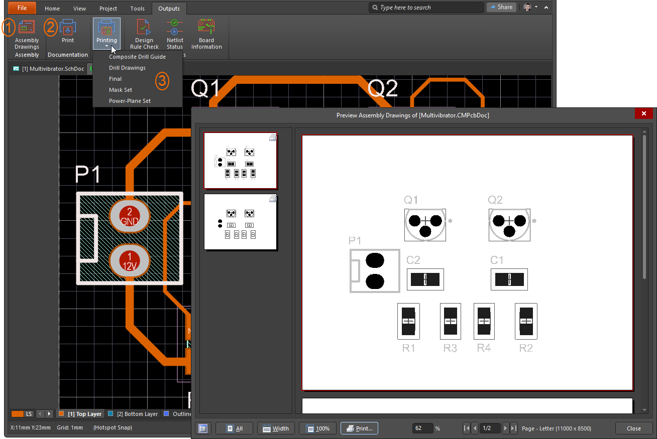
The Outputs | Documentation | Print command is used to configure and generate printouts. The active document is displayed in the preview window. Use the controls and options in the preview to configure the printout.
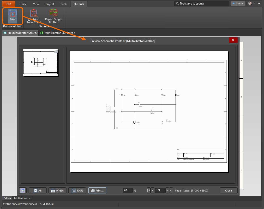
Additional options for a PCB document include:
During the course of developing a project, there are logical points, or milestones, in its progress where it is ‘released’ as a complete version, ready for fabrication and assembly. These are, essentially, stages in the project’s lifecycle when it has reached a state that’s ready to prototype or is, in fact, finalized as a production version that can be built by anyone.
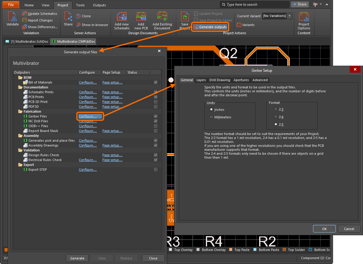
CircuitMaker caters to this need with the concept of a Project Release. A project release includes a choice of generated output files such as schematic/PCB printouts, part lists (BOM), fabrication and assembly files, etc. Select the Generate outputs command of the ribbon's Project tab to open the Generate output files dialog. Use the checkbox column to select the outputs you would like to generate and controls in the Configure and Page Setup columns to define settings for each output where applicable.
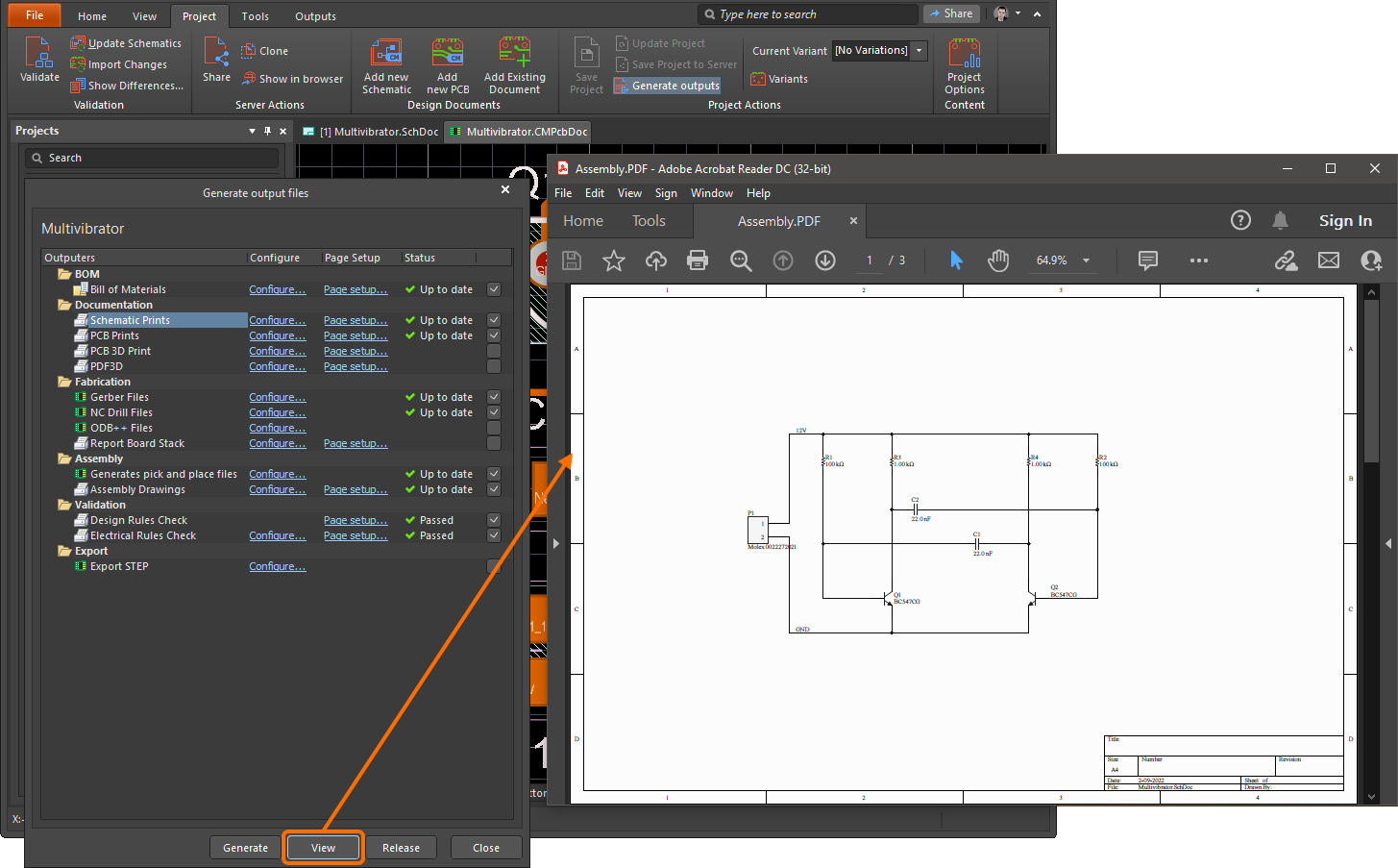
When outputs are configured, click the Generate button at the bottom of the Generate output files dialog to generate selected outputs. When done, Up to date will display in the Status column if an output has been generated successfully. Select an output in the list then click the View button to open that output to view it.
When the outputs are generated as needed, click the Release button then click OK in the Confirm Release dialog to execute the release.
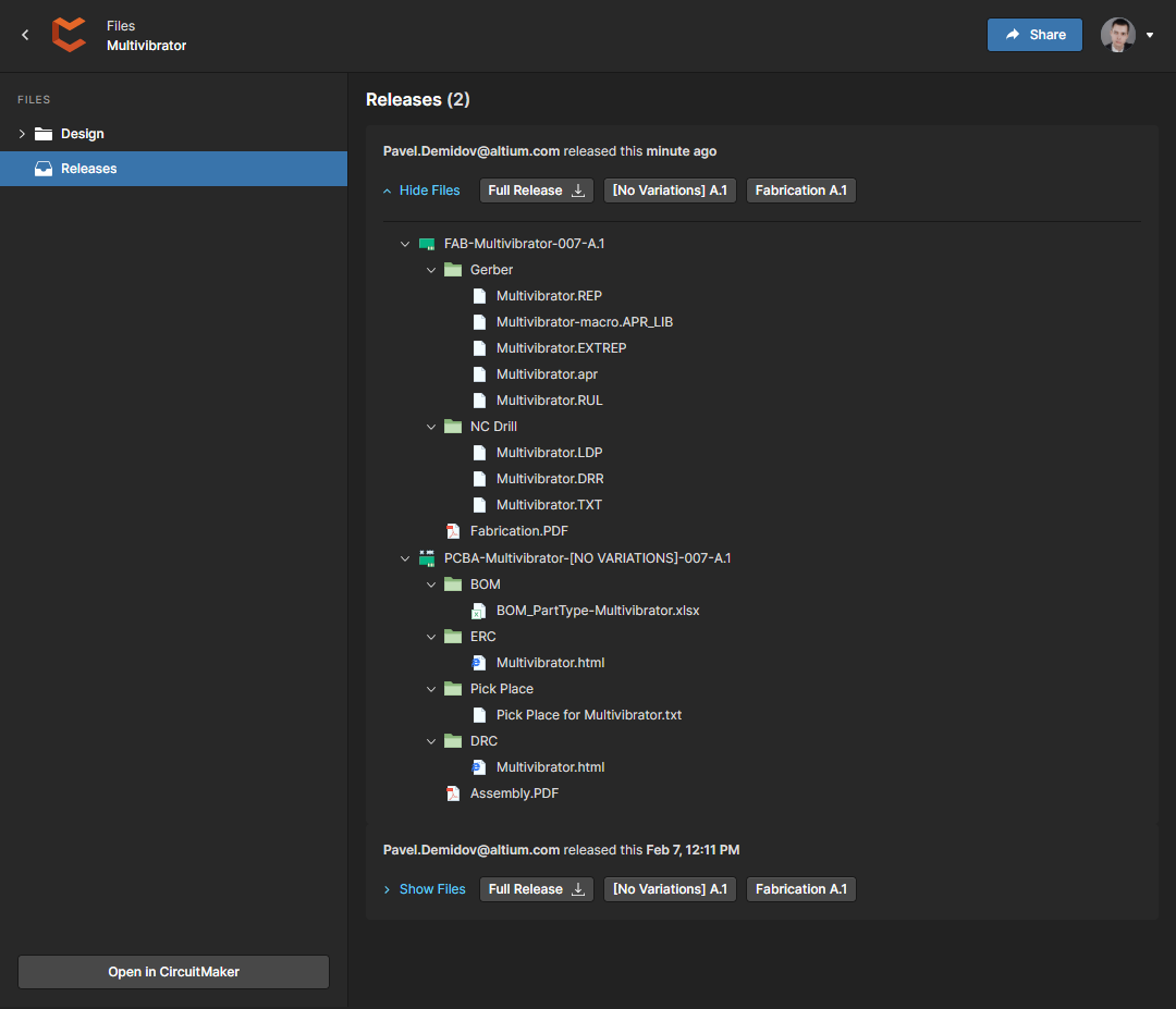
The outputs generated during project release will be available through the Releases view of the project in Altium 365's Web Viewer where a specific output, a group of outputs, or all outputs of a release can be downloaded.
Sometimes a PCB can be used to produce multiple product versions. The differences between the various options will consist of a set of components mounted on the board and will be included in the documentation.
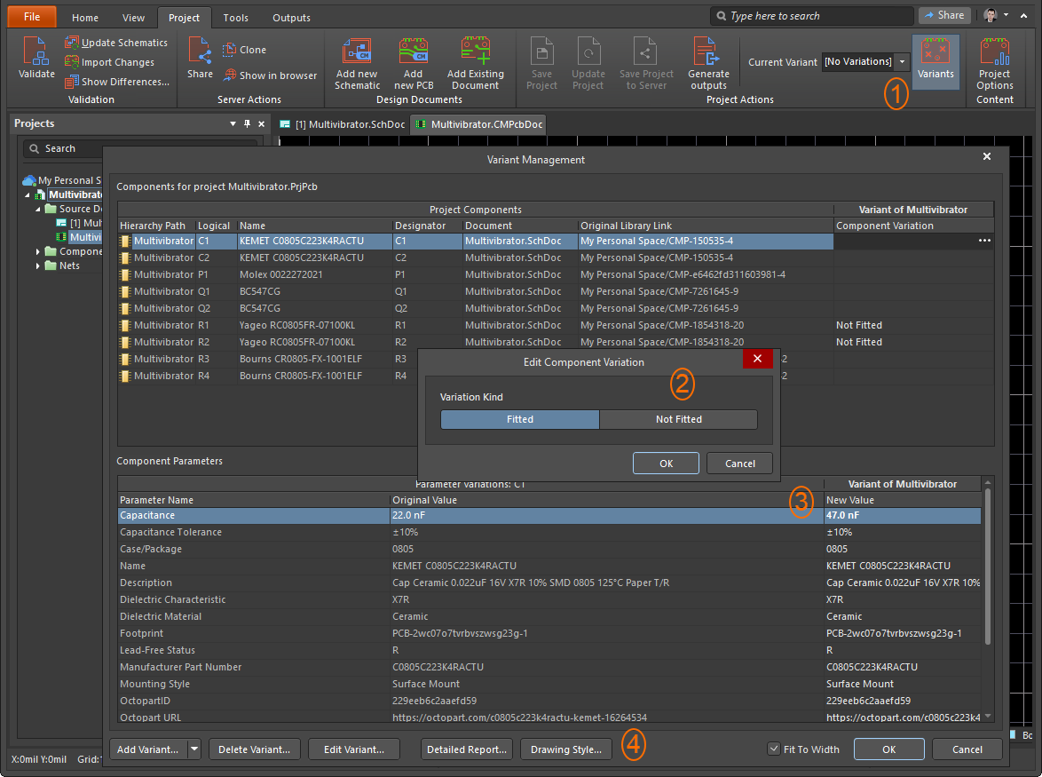
To create a new variant, use the Variants button (1) and the Variant Management dialog. The list of components that are fitted or not fitted are defined in the upper section for the created variant using the Edit Component Variation dialog (2). In the lower region, you can define an additional set of component parameters from the standard variant (3).
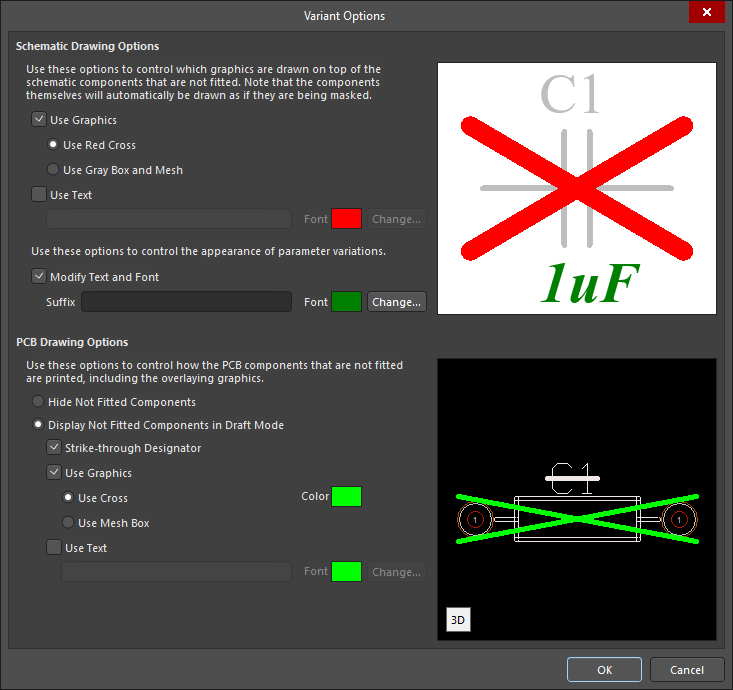
The settings for displaying variations of components are in the Variant Options dialog. This dialog is accessed using the Drawing Style button found in the Variant Management dialog (4 on the image above). The schematic drawing options consist of using a Red Cross, Gray Box, Mesh, and text addition. The font is configured for the modified component parameters. In the PCB editor, it is possible to hide components that are not fitted or use options such as Strike-through Designator, Use Graphics, and Use Text, as well as the ability to change the color and font.
Contact our corporate or local offices directly.
