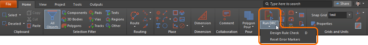
The Run DRC button and commands perform the following functions:
Runs a design rule check and creates a Design Rule Verification Report.
Opens the Design Rule Checker dialog.
Resets error markers in the PCB.
The commands can be accessed by choosing Home | Design Rules | Run DRC from the PCB editor.
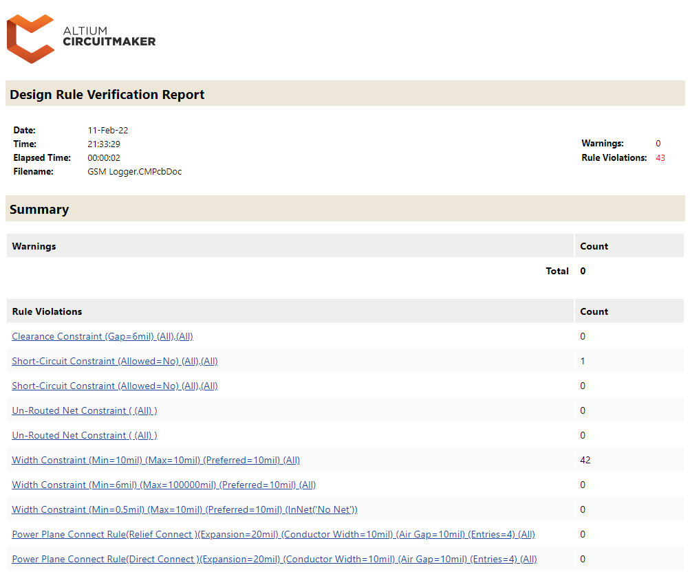
Click to run a design rule check in accordance with rules enabled for batch checking and additional options defined for this type of checking then open a Design Rule Verification Report. Design rule checking is a powerful automated feature that checks both the logical and physical integrity of a design. An example report is shown below.
Design Rule Checker Dialog
The Design Rule Checker dialog is accessed by choosing Home | Design Rules | Run DRC » Design Rule Check.
The dialog is also accessed by choosing Outputs | Reports | Design Rule Check.
This dialog allows you to configure design rule checking for the board. Checks are made against any or all enabled design rules and can be made online, during design, or as a batch process (with an optional report). This feature should be used on every routed board to confirm that minimum clearance rules have been maintained and that there are no other design violations. It is particularly recommended that a batch mode design rule check always be performed prior to generating final artwork.
Online Design Rule Checking runs in the background, in real-time, flagging and/or automatically preventing design rule violations. This is especially helpful when manually routing to immediately highlight clearance and width violations.
Online DRC only detects new violations (i.e. violations that are created after the feature is enabled), and batch DRC allows a check to be manually run at any time during the board design process. Board design should begin and end with a Batch DRC.
The dialog's functionality is divided into two areas:
Configuration of options relating to a batch DRC.
Configuration of which rules to check and whether those rules should be checked as part of the online and/or batch DRC.
These areas are reflected by and accessed through the folder-like entries in the left-hand pane.
Run Design Rule Check - click to perform a Batch DRC in accordance with rules enabled for batch checking and additional options defined for this type of checking.
After the check complete, all violations will appear in the Messages panel.
Report Options
Clicking on the Report Options folder loads the right-hand side of the dialog with additional options that are available when running a batch DRC.
DRC Report Options
Create Report File - enable to have a report generated after running a Batch DRC for the board.
The report is in HTML format and will be named Design Rule Check - PCBDocumentName.html. It will automatically be opened as the active document after the Batch DRC process has completed.
Create Violations - enable to have violations highlighted in the design space in accordance with defined violation display settings. This option is also required to have violations appear listed in the Violations region of the PCB Rules And Violations panel.
Management of how DRC violations are displayed (using custom violation graphics and/or a defined violation overlay) is configured on the PCB Editor - DRC Violations Display page of System Preferences.
Sub-Net Details - if an Un-Routed Net rule has been defined, enable this option to include sub-net details in the DRC report.
The Un-Routed Net rule should only be enabled for checking when all connections have been routed as a connection line is effectively an "open circuit".
Verify Shorting Copper - enable to verify the integrity of the shorting copper in any Net Tie components used in the design. This check looks for any unconnected copper in a component (indicative of a pad not shorting the other pad(s) correctly).
Report Drilled SMT Pads - enable to include any SMT (Surface Mount Technology) pads that have been erroneously drilled in the DRC Report.
An SMT pad can be, for example, a short pin; flat contact; one of a matrix of balls (BGAs); a termination on the body of a component (passives); or a short lead in a gull-wing formation (QFPs).
This option is only for detecting SMT pads with holes defined in them, which was possible in legacy versions of the software.
Report Multilayer Pads with 0 size Hole - enable to include any invalid multi-layer pads found in the design. An invalid multi-layer pad is one whose hole size is zero, which would otherwise make it an SMT pad.
Stop when n violations found - use to determine the maximum number of violations that can be detected before the batch DRC process is stopped (default = 500). Limiting the number of violations that are reported is a key strategy in keeping the checking process manageable.
Report Broken Planes - enable to have the batch rule checking process look for and report broken planes. Broken planes occur when an area of a plane that has connectivity to a net becomes electrically disconnected from the rest of the plane. An example of where this may occur is a connector placed across a split plane but is not connected to it. The voids around the pins join to completely cut through the plane copper, effectively breaking it into two parts.
To check for broken planes, the Un-Routed Net rule (Electrical category) must be enabled for Batch DRC.
Report Dead Copper larger than - enable to have the batch rule checking process look for and report dead copper regions larger than the specified area. Dead copper refers to sections of copper that have no connectivity to a net and that also becomes electrically disconnected from the original parent plane. An example of where this may occur is a connector (not connected to the plane) with closely spaced pins in which the voids around the pins join to isolate areas of plane copper from the rest of the plane. Use the associated field to specify a value for the minimum permissible area of dead copper beyond which is considered a rule breach (default = 100 sq. mils).
To check for dead copper, the Un-Routed Net rule (Electrical category) must be enabled for Batch DRC.
Report Starved Thermals with less than n% available copper - enable to have the batch rule checking process look for and report starved thermal connections larger than the specified percentage. Thermals are connections to a plane with thermal relief 'cutouts' around them to reduce heat conductivity to the plane copper. A thermal can become 'starved' when the surface area of the copper spokes connecting it to the plane is reduced by void areas. This option also checks the surface area for the thermal (not just the spokes) against any void areas that encroach into the thermal. Use the associated field to specify a value for the minimum permissible percentage of connecting copper that must remain below which is considered a rule breach (default = 50%).
Rules To Check
Clicking on the Rules To Check folder loads the right-hand side of the dialog with a list of all checkable rule types. Alternatively, click on a specific category below the folder to list only those design rule types associated with that category. Enable each rule type for Online and/or Batch checking as required.
Use the right-click menu to access commands to quickly enable/disable all rule types for Online or Batch DRC or only those rule types that are used (defined and enabled for use).
Notes
A generated Design Rule Verification Report lists each rule that was tested during the batch checking process. Each violation that was located is listed with full details of any reference information, such as the layer, net name, component designator, and pad number, as well as the location of the object. Click on the entry for an offending object to cross probe directly to that object in the design space.
To give further flexibility when displaying rule violations in the design space, the two violation display types (violation details (custom violation graphics) and violation overlay) have separate associated system colors. This allows you to differentiate between the two using different, distinct colors. Color assignment is performed in the View Configuration panel.
Violation Details – uses the color assigned to the Violation Markers system color.
Violation Overlay – uses the color assigned to the DRC Error Markers system color.
After running a Batch DRC, double-click on a violation message in the Messages panel to cross-probe to the object(s) causing that violation in the design space.
When running an Online or Batch DRC, any rule violations will be listed in the Violations region of the PCB Rules And Violations panel.
Violations associated with a particular design object can be interrogated directly within the PCB design space. Position the cursor over an offending object, right-click then choose a command from the Violations sub-menu. Either choose to investigate an individual violation in which the object is involved, or choose to view all violations in which it is involved using the Show All Violations command. In each case, the Violation Details dialog will open and provide detailed violation information and controls for highlighting and jumping to the offending object(s).
Reset Error Markers
Choose Home | Design Rules |Design Rule Check » Reset Error Markers to remove error markers. Note that this removes only the error markers, the underlying design rule violations must still be analyzed and resolved.