The Fusion 360 CoDesigner button is used to open the Fusion 360 CoDesigner panel, which is used to Push and Pull design changes back and forth between CircuitMaker and Autodesk® Fusion 360®. The button is accessed by choosing View | System | Fusion 360 CoDesigner from the PCB editor.
Passing Design Changes Between CircuitMaker and Autodesk Fusion 360
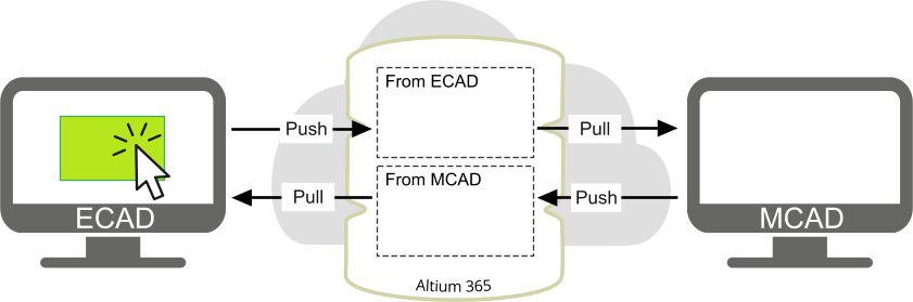
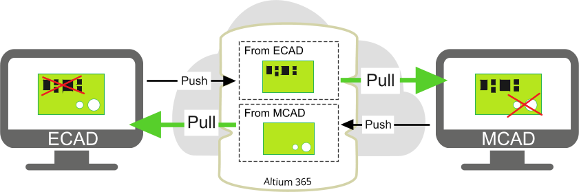
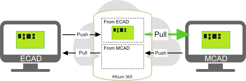
CoDesigner transfers the mechanical PCB assembly to ECAD through the Altium 365 platform. The changes that are Pushed/Pulled are directional - the PCB assembly Pushed from MCAD (and Pulled to ECAD) is stored separately on the Altium 365 platform from the PCB assembly Pushed from ECAD (and Pulled to MCAD).
ECAD and MCAD changes are stored separately on the Altium 365 platform.
Design changes are not transferred directly between the ECAD and MCAD environments, they are transferred through the Altium 365 platform. CircuitMaker projects are stored in an Altium 365 Personal Space, CoDesigner also uses this space to store a separate tool-neutral snapshot of the design that is accessible to both CircuitMaker and Autodesk Fusion 360. This approach allows designers on both sides to continue to edit their design files, and Push and Pull the updates when they are ready. The tool-neutral snapshot holds details of the objects that are supported by CoDesigner, not the entire board design.
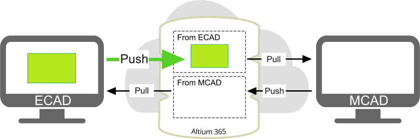
Push
Design changes created in either environment are transferred to the target environment by performing a Push in the source editor. A message can be included to explain the nature of the change, this message is displayed in the respective panel's target environment. The Send button is then clicked to push the board to the shared Altium 365 platform. The Pull button can then be clicked in the target editor to synchronize the ECAD and MCAD designs.
Send
When Send is clicked:
The working copy of the modified PCB file is automatically saved if it is currently unsaved.
The changes are written to the Altium 365 platform.
The Comment is displayed in the message thread of the source editor's CoDesigner panel.
The target editor's panel will display a message that there is a change pending the next time they open their working copy of the design file, as shown in the image below on the right.
Pull
To check at any time if there are changes pending, click Pull.
If there are changes pending the message, New changes have been detected will appear in the Fusion 360 CoDesigner panel in CircuitMaker, or the Altium CoDesigner panel in Fusion 360, as shown above.
When the Pull button is clicked a list of Changes will display, as shown in the image below. Each change is a difference between the data in the PCB file, and the data pushed by the source editor.
Enable the checkbox () for each change you wish to accept. Right-click in the list of Changes to access a context menu where all changes can be enabled or disabled.
Click the Apply button to apply those changes to the PCB.
Working Between CircuitMaker and Autodesk Fusion 360 as Different Users
If you're the engineer designing both the electronics and the mechanical design, you sign in to Altium Live from both CircuitMaker and Fusion 360. The process changes slightly if different engineers are working in each of the design tools. In this situation, the CircuitMaker engineer must Share the project with the Fusion 360 engineer.
To use CoDesigner with different engineers:
Both the CircuitMaker engineer and the Fusion 360 engineer must have their own Altium Live account, and use these to sign in to CoDesigner.
Because the project is stored in the CircuitMaker engineer's Personal Space, the CircuitMaker engineer must Share the project with the Fusion 360 engineer. Learn more about sharing a project with a specific user.
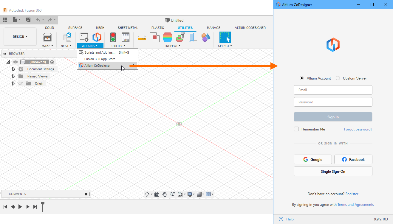
Launch Autodesk Fusion 360 and confirm that the Add-In is installed and available in the Add-Ins section of the Tools ribbon, as shown below.
The CoDesigner Add-In adds the Altium CoDesigner panel to Autodesk Fusion 360. All collaboration activities are performed through this panel.
Displaying the CoDesigner Panel
In Autodesk Fusion 360, the Altium CoDesigner panel can be enabled by clicking the Altium CoDesigner menu entry or button, as shown above.
Connecting to the Altium 365 platform in Autodesk Fusion 360
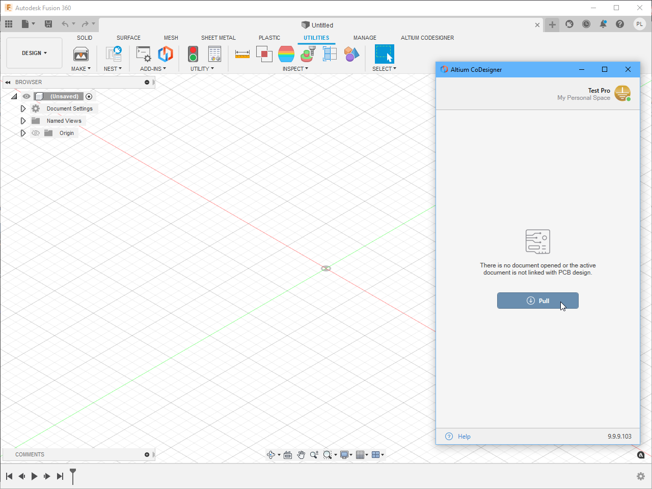
Autodesk Fusion 360 collaborates with CircuitMaker through the Altium 365 platform, which you must sign in to the first time you use it.
When you are not signed in, the Altium CoDesigner panel will include sign-in fields, as shown below. There is one sign-in mode, which allows you to sign into the Altium 365 platform.
Select the Altium Account option in the Altium CoDesigner panel.
Enter the email address you use to sign in to Altium Live as your Email and your Altium Live Password.
Enable the Remember Me option to retain the details (including the password) and automatically connect to the Altium 365 platform each time Autodesk Fusion 360 is started.
Click the Sign In button to connect
Once you have signed in, you are ready to start collaborating through Altium CoDesigner.
Configuring the Fusion 360 Collaboration Settings
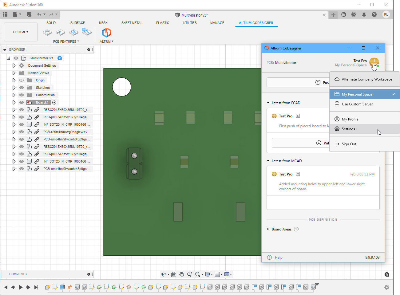
Once you have signed in, CoDesigner settings can be configured in the Altium CoDesigner Settings dialog, opened via the Settings menu entry in the CoDesigner menu.
Ignore components smaller than <Value><Units> in height - the performance of Fusion 360 is affected by the number of components on the PCB. Use this option to exclude components that have a height of less than <Value><Units> when a Pull is performed. Note that the height is the Height property defined in each CircuitMaker component, it is not the height of the 3D model that might be included in the PCB component. Set this option to zero to include all components.
This section details the functionality and behaviors that the mechanical engineer should be aware of when using CoDesigner.
Managing the Synchronization Process
ECAD and MCAD push their changes to different storage locations on the Altium 365 platform. That means each engineer can only pull changes that have been pushed by the other engineer. Those changes will only include their own changes if they’ve already been accepted by the other engineer before the other engineer has pushed.
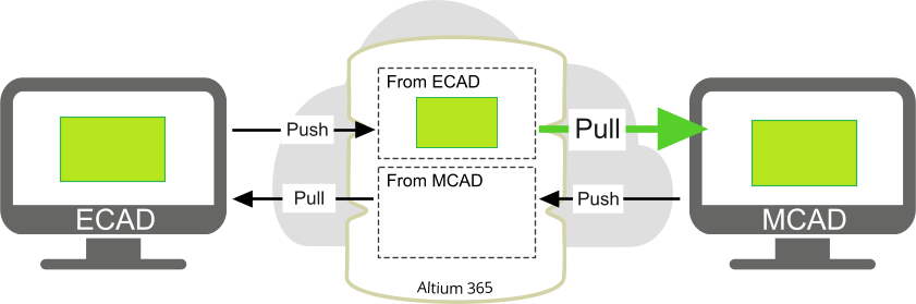
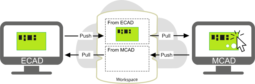
For example, a board is created in ECAD, Pushed to the Altium 365 platform, and Pulled to MCAD:
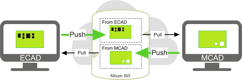
If the ECAD engineer then adds components AND the MCAD engineer adds holes, AND if each Pushes their board then Pulls the other’s board, CoDesigner will try to remove the holes in the MCAD engineer's board, and remove the components on the ECAD engineer's board:
Each engineer does have the option to reject specific proposed changes, for example, the ECAD engineer could accept the addition of the holes but reject the deletion of the removed components. However, working in this way can be hard to manage with complex boards and/or changes. Another point is that all changes to the decals are only seen by CoDesigner as a single change, so can only be accepted or rejected as a whole, not individually.
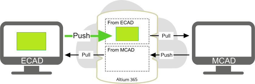
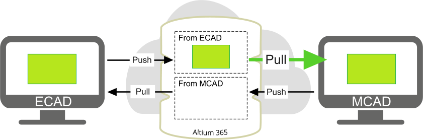
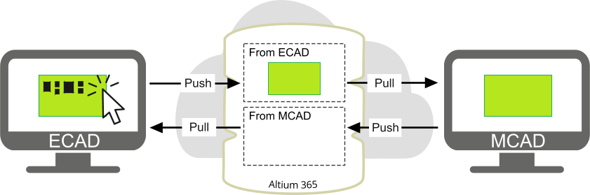
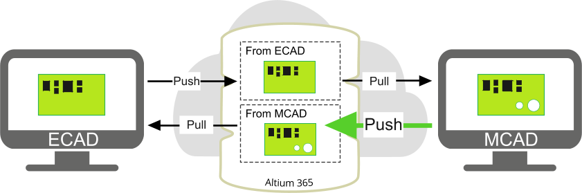
A better approach is for one engineer to make their changes and push the board, then for the other engineer to pull the board before making their changes, as shown below:
Synchronizing Changes Between Mechanical Engineers
CoDesigner transfers the mechanical PCB assembly to ECAD through the Altium 365 platform. The changes that are Pushed/Pulled are directional - the PCB assembly Pushed from MCAD (and Pulled to ECAD) is stored separately on the Altium 365 platform from the PCB assembly Pushed from ECAD (and Pulled to MCAD). That means a second mechanical engineer cannot Pull the modified board that a mechanical engineer just Pushed to the Altium 365 platform, instead they will be Pulling the last-pushed ECAD data. To allow other mechanical engineers to see your changes, save your PCB assembly in the same way as you do for any other assembly - to common storage available for both engineers. This method will preserve any MCAD constraints. Alternatively, get the ECAD designer to Pull the data into CircuitMaker, save it, and then Push the updated design back to MCAD. However, as explained below, no MCAD constraints will be included if you use this second approach.
ECAD and MCAD changes are stored separately on the Altium 365 platform.
Note that MCAD constraints exist only in the MCAD assembly in which they were created. When the board is pushed from MCAD to ECAD, the component positions resulting from the constraints are pushed, but not the constraints themselves. Therefore if the board is pulled into a new MCAD assembly, none of the constraints created by a previous MCAD engineer will be included.
Another important point is that changes made to the same PCB assembly by different mechanical engineers are not merged when they are Pushed, the latest change Pushed by any mechanical engineer will overwrite previous changes Pushed by other mechanical engineers.
Visibility of Changes Made on the ECAD side
It is important to open the PCB assembly itself in your MCAD software, not the parent device/assembly that the PCB assembly is being designed to fit in. If the PCB assembly is opened, changes made and pushed from the ECAD side will be detailed in the Altium CoDesigner panel. Changes will not be detailed in the panel if the parent device/assembly is opened.
Getting Changes to your PCB Assembly from ECAD
Open your PCB assembly as a separate file (as a root assembly) in MCAD.
Open the Altium CoDesigner panel.
Click Pull.
Review the changes in the table, enable the ones you want to be applied, and click the Apply button.
Before being transferred from ECAD to MCAD, the 3D component models are transformed to the Parasolid format. There may be situations where some of the models can not be transformed. Such models are replaced with their bounding box in MCAD, and CoDesigner shows a warning message about this.
Alternatively, you can replace such a model with a single-body parasolid model in ECAD, as these are transferred directly between ECAD and MCAD without transformation.
When you have a PCB Assembly Open in MCAD for the First Time
Add the PCB assembly to your device’s assembly.
Secure it by applying suitable mates/constraints.
If a contour of the PCB does not correspond to the shape of your enclosure:
Start editing the Board part.
Edit the sketch of the board’s extrusion and adjust its shape to the enclosure.
Notes:
One approach to changing the PCB shape is to delete the whole outline and to create it from scratch using an offset from the corresponding contour of your enclosure.
Making Changes to the PCB Design in MCAD
Below are some tips for ensuring the design shapes and objects used in MCAD will be supported when the board is pushed to ECAD.
Editing the board outline shape:
Start editing the Board part.
Edit the sketch of the board’s extrusion.
Notes:
Do not include any internal contours in the board outline sketch in Creo and Inventor, or in the rigid-flex board outline sketch in SolidWorks. For cutouts and holes, use the Extruded Cut or the Hole feature, accordingly.
Do not create multiple profiles in the board outline sketch in Inventor, CoDesigner can interpret them in an unpredictable manner.
Changing the MCAD Board Origin:
If necessary, the mechanical engineer can change the MCAD origin of a bare board in the early stages of the board definition. To do that, the mechanical engineer can simply move or redraw the entire sketch of the board outline, within the board part. Note that the board part is constrained as “fixed” within the board assembly, with its origin coincident with that of the assembly (therefore “MCAD origin” relates to both the board part origin and the board assembly origin). It’s strongly recommended that this constraint is NOT modified or broken, because it may cause unpredictable changes.
Notes:
If components are already placed, they should be moved within the board assembly, accordingly.
The “electrical” board origin in ECAD will not be changed, as it is handled separately.
Creating/editing Mounting Holes:
Start editing the Board part.
Create/edit a Hole feature on the top or the bottom surface of the board part.
Notes:
Feature patterns are not supported. All entities included in a pattern will be transferred from MCAD to ECAD and back, however, if any entity within a pattern is changed in ECAD, the pattern will be broken.*
If the hole locations are defined in relation to the board edge, these relations will be destroyed if the board outline is subsequently modified in ECAD and brought back into MCAD. See the section Working with Constraints and Dimensions below, for more information on working with holes.
Creating/editing Cutouts:
Start editing the Board part.
Create/edit an Extruded Cut feature based on the top or the bottom surface of the board part.
Notes:
Sketches with multiple contours are not supported in PTC Creo or Autodesk Inventor, they should not be used.*
Feature patterns are not supported. All entities included in a pattern will be transferred from MCAD to ECAD and back, however, if any entity within a pattern is changed in ECAD, the pattern will be broken.*
If the sketch of the extruded cut is defined in relation to the board edge, these relations will be destroyed if the board outline is subsequently modified in ECAD and brought back into MCAD.
Editing the placement of components:
Start editing the Board assembly.
Move/rotate/flip, or mate/constrain a component.
Notes:
Component holes and the silkscreen do not follow component moves in MCAD. To reflect component-dependent changes like these; Push the board to ECAD, apply the changes there, then Push the board from ECAD back to MCAD to update the component holes and silkscreen.
MCAD mates/constraints that reference a board edge can be destroyed if the board shape is modified in ECAD.
Synchronizing Fixed or Constrained in MCAD to Locked in ECAD
If a component is fixed or constrained in MCAD, it becomes locked in ECAD (regardless of if that constraint allows any movements within the PCB assembly or not). If a component is locked in ECAD, it becomes fixed in MCAD unless it is already constrained there. Changes in the locked/fixed state are synchronized between MCAD and ECAD.
Transferring ECAD Component Parameters to MCAD
ECAD PCB component parameters are transferred to the corresponding models created in MCAD. Note that this does not include components that were originally placed in MCAD.
Working with Constraints and Dimensions in MCAD
Constraints applied to the board outline:
The mechanical engineer can apply a constraint from an element of the board outline: to another board outline element; to a datum/reference feature; to a part in a higher level assembly; or to a component. CoDesigner does not modify these constraints. However, if the board outline is changed on the ECAD side, the sketch of the board part will be redrawn in MCAD and all of the edge IDs will be changed. Note that any change to any part of the board outline in ECAD will result in the entire board being redrawn in MCAD, and all board edge IDs changing. If there was a constraint applied to those edges or to the derived surfaces, those constraints will be broken. The board will stay in place in MCAD, and if necessary, the constraints can be manually restored. But considering that this will take some time, it is better to make changes to the board outline on the MCAD side only.
The mechanical engineer can apply a constraint from a component: to the board; to an enclosure; or to another component. These constraints will stay healthy if the model of that component can be found locally (if the PCB assembly is not built from scratch in a different folder, or if a common folder is set up for storing models). However, if a component is moved on the ECAD side, the placement change on the MCAD side may not correspond to that movement and should be checked manually (CoDesigner will notify you in this situation). For components with an ECAD footprint, the component standoff (location relative to the board surface in the Z direction) will always be defined by the position of the STEP model in the footprint. CoDesigner will always attempt to override any conflicting MCAD constraints on a Pull into MCAD.
Note: Be careful with where the mates/constraints are applied. For example, if you have not secured the PCB assembly within the device assembly and then applied a constraint/mate between a PCB component and the enclosure, it may cause unpredictable changes in your design.
Changes that will Not be Transferred from MCAD to ECAD
Bare Board thickness - defined by the Layer Stack in ECAD.
Note: the changes made to the board thickness in MCAD will be shown as a non-applicable change in ECAD, so the ECAD designer will be aware of the change being proposed.
Any additional geometric features applied to the board part (eg. 3D chamfers/fillets), except for holes and extruded cuts in the board's z-axis direction.
Any additional geometric features created in the context of the board assembly (eg. holes created in the context of an assembly), unless these features are propagated to parts.
The location of component holes if they are moved separately from the component.


 ECAD and MCAD changes are stored separately on the Altium 365 platform.