 Search feature
Contact Us
Contact our corporate or local offices directly.

The electronic product you hold in your hand is the melding of numerous, independent designs. Firstly there's the enclosure you're holding; inside that, there will be one or more electronic circuit boards, and on the board, there is often a microprocessor running software. Beyond that, there can be specialized sections of circuitry to perform unusual sensing or signal transmission, or programmable hardware to implement high-speed signal processing.
Each of these independent designs - the mechanical enclosure, the electronic circuit, the printed circuit board, the microprocessor code, and the programmable hardware - uses its own design paradigm, with each design crafted through its own design editor.
Over many years these unique design spaces have become more closely connected. This close connection is essential to ensure that all aspects of the final product correctly interface with each other, delivering to us those easy-to-use and familiar products such as our mobile phone, our laptop, and our electric car.
The ECAD-to-MCAD divide is the last of these design spaces to be bridged. Bridging them by saving files in an intermediate file format works, but is becoming inadequate - being error-prone, limited in functionality, and difficult to coordinate and manage.
What is needed is a true 3D PCB design editor, which can directly communicate design changes to a variety of mechanical design packages. This challenge is being solved by Altium CoDesigner, technology from Altium that is bringing the ECAD and MCAD design domains together.
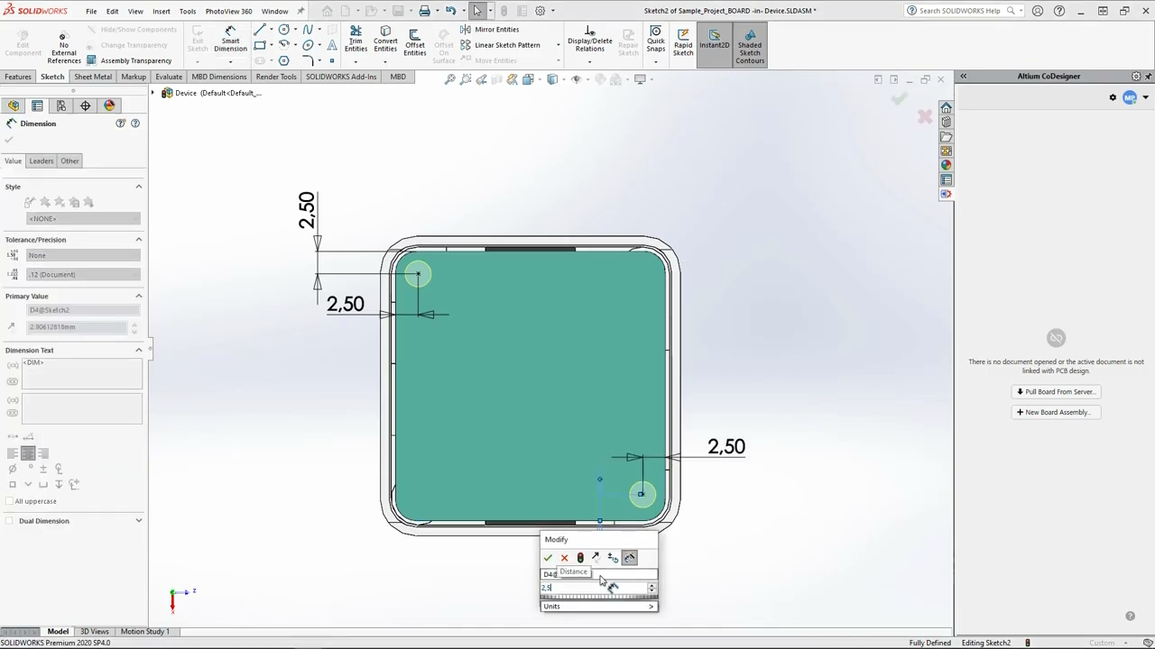
 If you're using CoDesigner to pass your board design back and forth to your mechanical engineer, then you'll want to know about the 3D design capabilities available in Altium's PCB editor. As well as creating or importing 3D models of the components, you can also import the product case and perform 3D clearance checking (hover the cursor over the image).
For a rigid-flex design the board can be interactively folded in the PCB editor, ideal for performing clearance checking of the folded board in its final state.
And if your MCAD software is not supported by CoDesigner yet, you can export the ECAD board in the STEP or Parasolid format, ready to load into your MCAD software.
► Learn more about the 3D Design Features in the PCB Editor
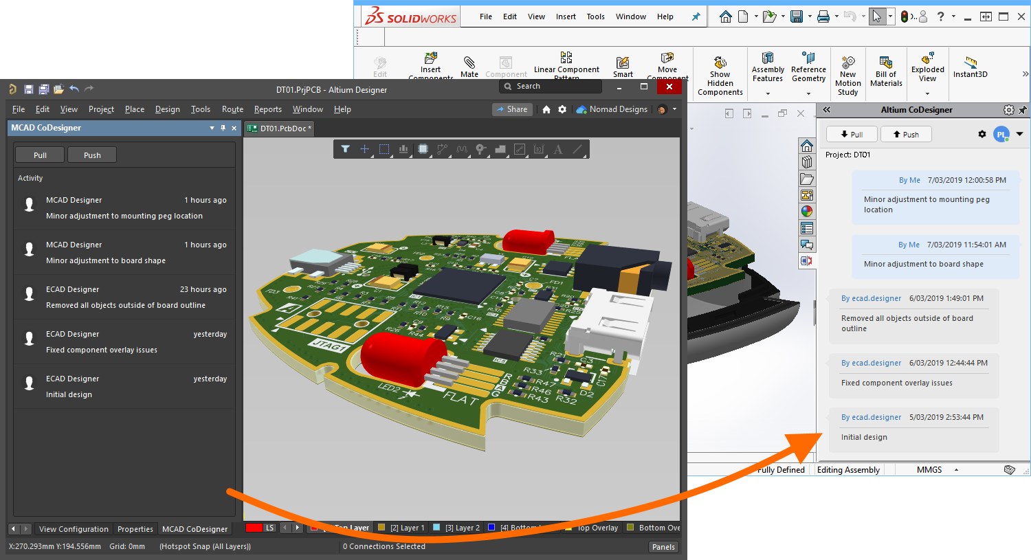
Working between the electronic and mechanical design domains brings unique challenges. Small and complex product enclosures that house multiple, irregular shaped printed circuit boards - to successfully design these products the ECAD and MCAD designers must be able to fluidly pass design changes back and forth between their design domains.
Passing complex and detailed design changes between different design software is much more than just being able to save data in another format. The electronic and mechanical design teams work independently and need to be able to selectively transfer design changes at any point in their design process.
Altium CoDesigner supports this, delivering direct ECAD-to-MCAD CoDesign.
► Learn more about Direct ECAD-MCAD Design with Altium CoDesigner
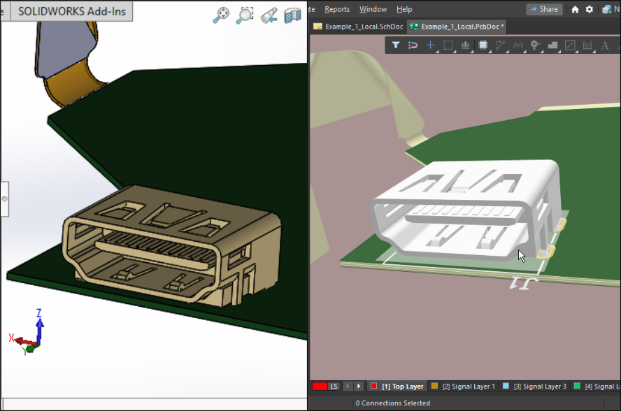 Each design software package represents and stores the design objects that it supports in its own way. Altium CoDesigner's default approach is to pass the components back and forth as 3D models in the standard Parasolid format, ensuring the design is mechanically accurate in both the ECAD and MCAD domains.
However, components are much more than their physical envelope. For example, in the PCB domain, they also hold silkscreen and paste detail, a link to their schematic symbol, as well as parametric information that couples them into the supply chain. In an ideal world, the ECAD and MCAD designers can each place a native design component from their own library, and link their native components to each other. This can be achieved, through their shared Altium 365 Workspace.
► Learn more about Linking Native ECAD and MCAD Design Components
Synchronizing a Rigid-Flex BoardPerhaps the most challenging printed circuit board design to bring to production is a rigid-flex design. Designing a rigid-flex circuit is very much an electromechanical process, because the rigid-flex board must be designed to be assembled and folded into the housing during product assembly. To date, this tight electro-mechanical design challenge has been solved by making a mechanical mock-up, also known as a paper doll cut out.
Altium CoDesign helps solve this challenge, delivering the ability to transfer the folded rigid-flex design between the ECAD and MCAD domains.
► Learn more about Synchronizing a Rigid-flex Board
Do you prefer to learn by watching? Then you might want to check out the growing collection of ECAD-MCAD Video Tutorials. Each video is a quick overview of how to solve a specific design challenge, such as Shaping the PCB in MCAD, or Maintaining the MCAD Constraints During Design Exchange.
► Watch the ECAD-MCAD Video Tutorials
If you're new to Altium software, you might like to start with the concept to completion tutorial - based around a simple nine-component circuit, you'll start with a blank schematic sheet and end up with the PCB, along with the files needed to fabricate the board. Like all of Altium's design technologies, the editors are designed to be quick to learn and easy to work in. Context-sensitive right-click menus are used extensively, and context-sensitive help (F1) and in-command shortcut lists (Shift+F1) are available everywhere.
Otherwise, you might like to check out the following articles:
Contact our corporate or local offices directly.